![]()

APPLICATION
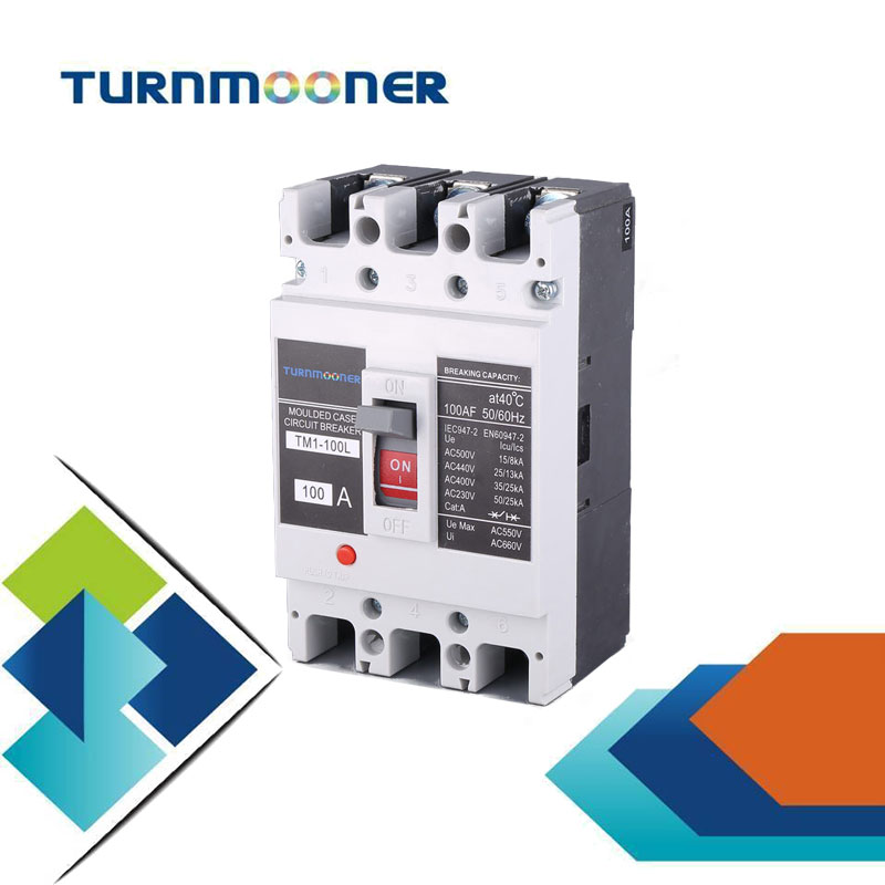
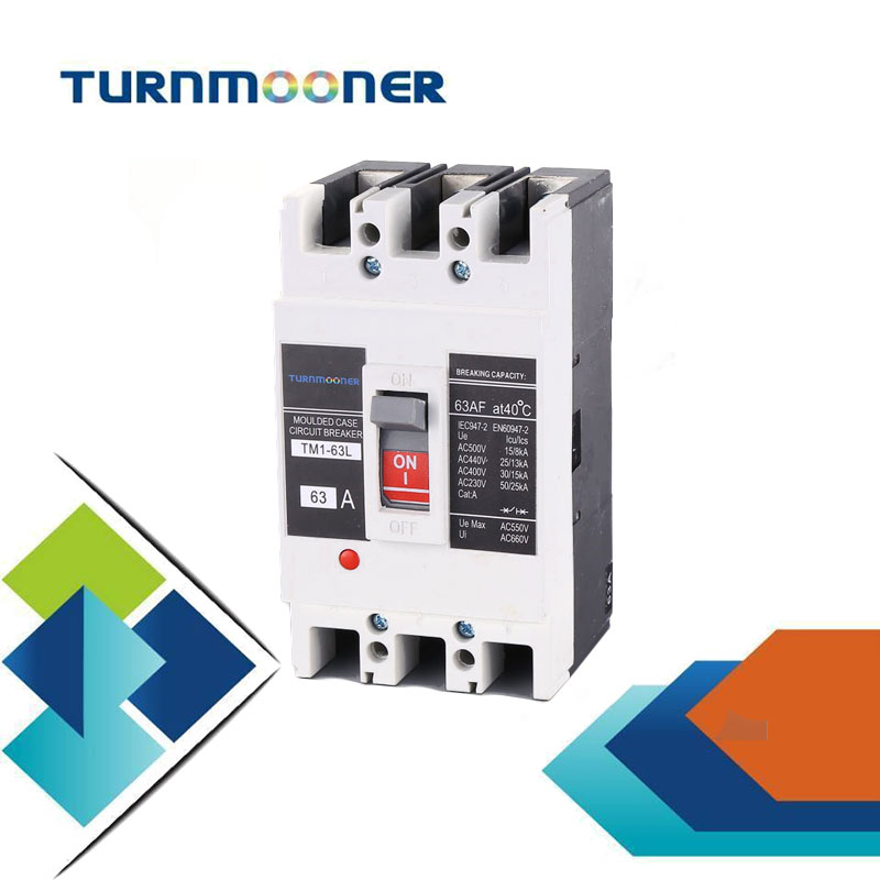
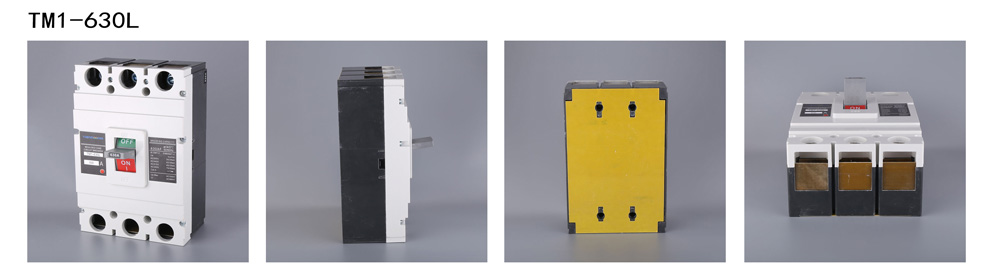
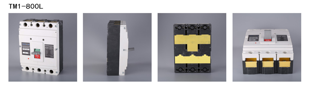
●TM1 series moulded case circuit breaker (named as MCCB in the following ) is a new type breaker which is applied with rated insulating voltage 800V(500V forTM1-63),rated working voltage 690V for TM1-63 and used for infrequent exchange and startup in AC(60)Hz condition. The MCCB is of protecting functioin in overloading, short-circuit, and under voltage situation to protect circuit system and power device from damage.
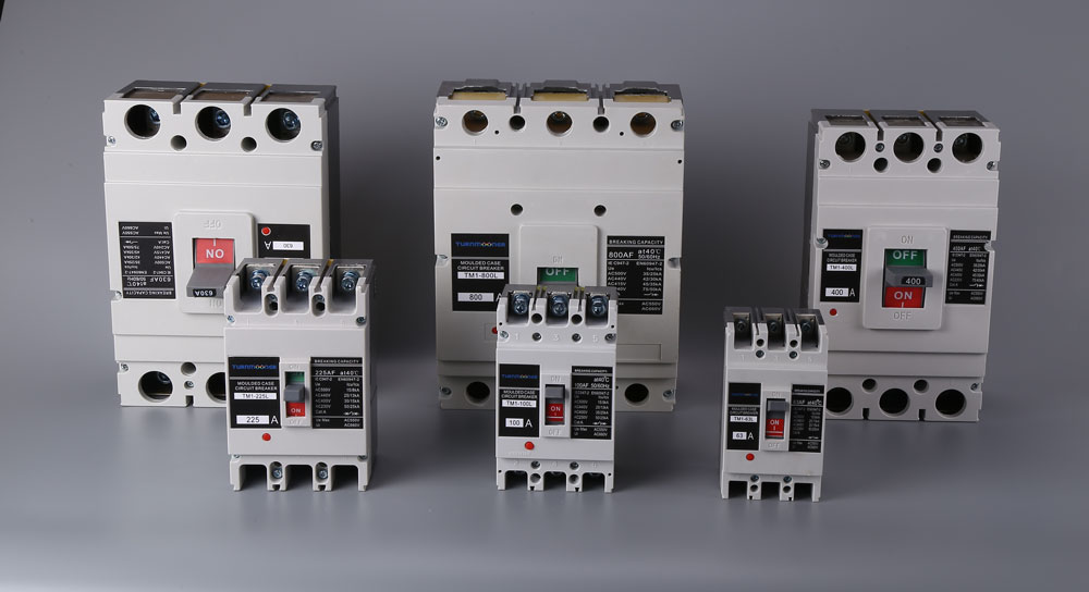
●The MCCB can be devided into L; M; H types according to their rated limit short-circuit breaking capacity.
●The MCCB is advantageous for its compact body,high breaking capacity (some even on flying arc), short arc-casting and superior aseismatic function.
●The MCCB has function of insulation with its mark" "
"
●The product complies with IEC60947-2、 GB14048.2.
TYPE CODE & SIGNIFICATION

1.N-P type from 4-P has 3 types:
A type: N-P without current tripper (normally open);
B type: N-P without current tripper working together with other 3P;
C type: N-P without current tripper working together with other 3P;
2.No code for distribution type breakers,2 for motor-protection type;
3.No-code for distribution type breakers,2 for motor-protection type;
4.It can be divided into L(common)type,M(standard)type and H(high) type.L type with connecting current equal to relevant frame level and M type with breaking capacity equaling to their frame level according to their rated limited short-circuit breaking capacity(Icu).
NORMAL WO RKING SITUATION
●Altitude 2000m and below;
●Ambient temperature no higher than+40℃
(45C for watercraft) no less than-5℃;
●Stand moist air;
Stand salty&oil mildew;
●Most gradient 22.50;
●Atmosphere without corrupt&electric air and;
no danger of explosion;
●Without rain effect.
TRIPPING CHARACTER Table 1:tripping characteristic
Rated tripping current (A) | Thermal tripper(Temperature 40℃) | E-magnetic tripping current(A) | Remarks | |
1.05In(cold)un-working duration (h) | 1.30In(hot)un-working duration (h) | |||
10≤In≤63 | 1 | 1 | 10lnX(1±20%) | Distribution type |
63<In≤100 | 2 | 2 | 10InX(1±20%) | |
100<In≤800 | 2 | 2 | 5|nX(1±20%) 10lnX(1±20%) | |
10<In≤630 | 1.01ln(cold)un-working duration (h) | 1.30ln(hot)un-working duration (h) | 12InX(1±20%) | Motor-protection type |
2 | 2 | |||
POWER LOSS
Table 2:MCCB power loss reference
Type | Current(A) | 3 Pole power loss(W) | ||
Back、front wiring | Plug-in front wiring | Plug-in back wiring | ||
TM1-63(L、M) | 63 | 20 | - | 24 |
TM1-100(L、M) | 100 | 35 | 37 | 40 |
TM1-225(L、M) | 225 | 62 | 66 | 70 |
TM1-250(L、M) | 250 | 67 | 73 | 73 |
TM1-400(M、H) | 400 | 115 | 120 | 125 |
TM1-630(M、H) | 630 | 187 | - | 200 |
TM1-800(H) | 800 | 262 | - | - |
DERATING FACTOR
Table 3: shipcraft type MCCB derating factor
Type | Derating factor (In) | ||||
+40℃ Shipcraft+45℃ | 45℃ Shipcraft+50℃ | 50℃ Shipcraft+55℃ | 55℃ Shipcraft+60℃ | 60℃ Shipcraft+65℃ | |
TM1-63 | 1 | 0.94 | 0.88 | 0.81 | 0.74 |
TM1- 100 | 1 | 0.96 | 0.91 | 0.85 | 0.78 |
TM1-225 | 1 | 0.94 | 0.94 | 0.9 | 0.86 |
TM1-250 | 1 | 0.94 | 0.94 | 0.9 | 0.86 |
TM1-400 | 1 | 0.95 | 0.89 | 0.82 | 0.75 |
TM1-630 | 1 | 0.94 | 0.88 | 0.82 | 0.76 |
TM1-800 | 1 | 0.94 | 0.87 | 0.8 | 0.72 |
Note: The above derating factors are got by rated frame level current
MAIN TECHNIQU E DATA OF MCCB
Mark4:MCCB main technique data reference
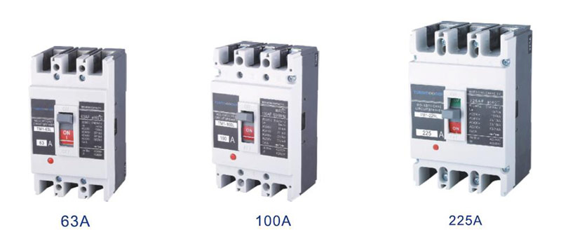
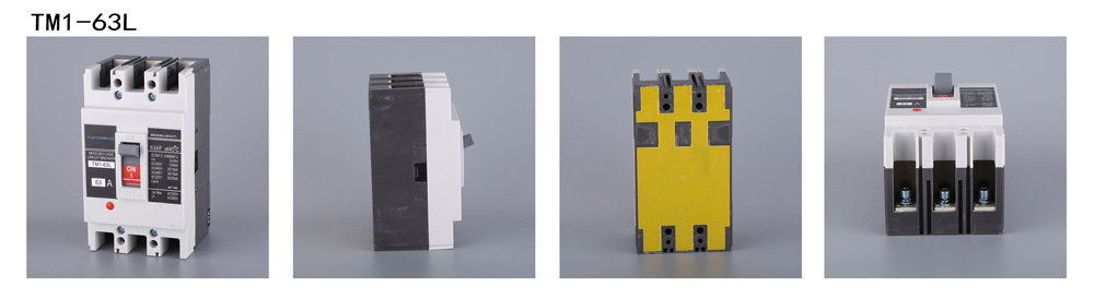
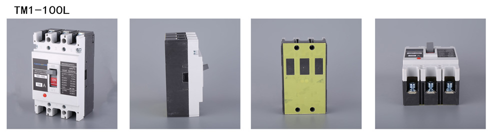
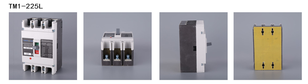
TYPE | TM1-63L TM1-63M | TM1-100L TM1-100M | TM1-225L TM1-225M | TM1-250L TM1-250M | |||||||||||
Rated frame level current Inm(A) | 63 | 100 | 225 | ||||||||||||
Rated current In(A) | 10、 12、16、 20、25、32、 40、50、63 | 16、20、25、 32、40、50、 63、80、100 | 125、160、 180、 200、 225、 (250) | ||||||||||||
Rated insulated voltage Ui(AC V) | 500 | 800 | 800 | ||||||||||||
Rated impulse-stand voltage Uimp(V) | 8000 | 8000 | 8000 | ||||||||||||
Rated working voltage Ue(AC V) | 400/415 | 400/415 | 400/415 | ||||||||||||
Poles | 3 | 4 | 3 | 4 | 3 | 4 | |||||||||
Rated limited shout-circuit breaking capacity level | L | M | L | M | L | M | L | M | L | M | L | M | |||
Rated limited short-circuit breaking capacity Icu(KA) | 400V/415V | 20 | 30 | 20 | 30 | 30 | 50 | 30 | 50 | 35 | 50 | 35 | 50 | ||
Rated working short circuit breaking capacity Ics(KA) | 400V/415V | 15 | 22.5 | 15 | 22.5 | 22.5 | 37.5 | 22.5 | 37.5 | 26.25 | 37.5 | 26.25 | 37.5 | ||
Operation characteristic (Times) | Connected | 2000 | 2000 | 1500 | |||||||||||
Break | 10000 | 10000 | 8500 | ||||||||||||
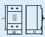
Outlook dimension |  | L | 135 | 150 | 165 | ||||||||||
W | 78 | 103 | 92 | 122 | 107 | 142 | |||||||||
H | 73.5 | 81.5 | 72 | 88 | 86 | 103 | |||||||||
Weight (g) | 735 | 849 | 1464 | 1952 | 1257 | 1493 | 1493 | 1900 | 1714 | 2014 | 1900 | 2014 | |||
Arcing distance ( mm) | 0、≤50 | 0、≤50 | 0、≤50 | ||||||||||||
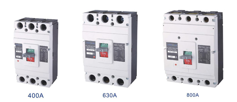
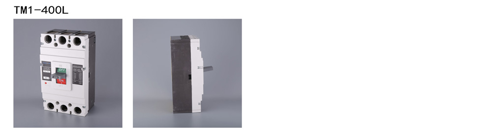
TYPE | TM1-400M TM1-400H | TM1-630M TM1-630H | TM1-800H | ||||||||||
Rated frame level current Inm (A) | 400 | 630 | 800 | ||||||||||
Rated current In (A) | 225、250、 315、 350、400 | 400、500、630 | 630、700、 800 | ||||||||||
Rated insulated voltage Ui (AC V) | 800 | 800 | 800 | ||||||||||
Rated impulse-stand voltage Uimp (V) | 8000 | 8000 | 8000 | ||||||||||
Rated working voltage Ue (AC V) | 400/415 | 400/415 | 400/415 | ||||||||||
Poles | 3 | 4 | 3 | 4 | 3 | 4 | |||||||
Rated limited shout-circuit breaking capacity level | L | M | L | M | L | M | L | M | H | H | |||
Rated limited short-circuit breaking capacity Icu(KA) | 400V/415V | 50 | 70 | 50 | 70 | 50 | 70 | 50 | 70 | 80 | 80 | ||
Rated working short circuit breaking capacity Ics(KA) | 400V/415V | 37.5 | 52.5 | 37.5 | 52.5 | 37.5 | 52.5 | 37.5 | 52.5 | 60 | 60 | ||
Operation characteristic (Times) | Connected | 1000 | 1000 | 500 | |||||||||
Break | 5000 | 4000 | 3000 | ||||||||||
Outlook dimension |
| L | 257 | 270 | 280 | ||||||||
W | 150 | 198 | 182 | 240 | 210 | 280 | |||||||
H | 106.5 | 110 | 115.5 | ||||||||||
Weight (g) | 5420 | 7443 | 6116 | 7116 | 7116 | 9929 | 8526 | 11731 | |||||
Arcing distance ( mm) | 0、≤50 | 0、≤100 | 0、≤100 | ||||||||||
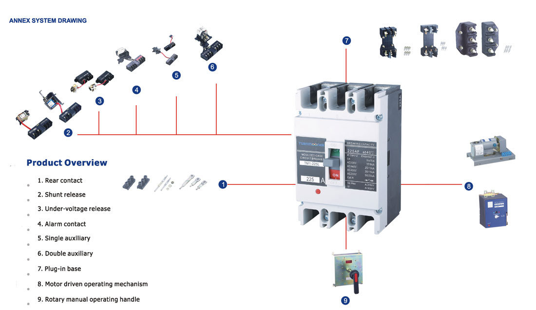
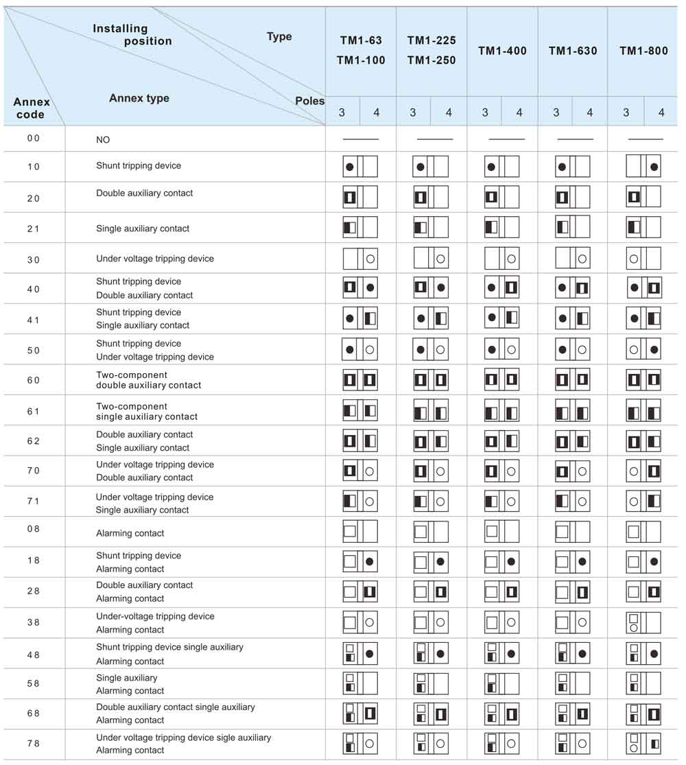
ANNEX SERIES
1.Annex code comparison table

Table4: Annex code comparison table
2.Auxiliary contact
Table 5: Auxiliary contact and assemblies
In the position of“open”or“free trip”for breaker | Double auxiliary contact | 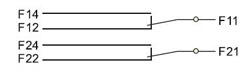 |
Single auxiliary contact | 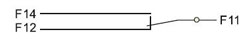 | |
In the position of“close”for breaker | “close”turn to“disconnect”、“disconnect" turn to“close”A | |
3.Auxiliary contact technical parameter
Table 6: Auxiliary contact current parameter
Shell rated current | Conventional the mal current 1th | AC 400V rated working current |
Inm≤225 | 3A | 0.30A |
Inm≥225 | 3A | 0.40A |
Table 7: Auxiliary contact electric life
Type of application | Connecting | Breaking | Times | Operation frequency (time/hour) | Conduction time | ||||
l/le | U/Ue | COSφ | l/le | U/Ue | COSφ | ||||
AC-15 | 10 | 1 | 0.3 | 1 | 1 | 0.3 | 6050 | 360 | ≥0.05s |
DC-13 | 1 | 1 | 6Pe | 1 | 1 | 6Pe | ≥T0.95 | ||
Table 8: Auxiliary contact connecting and breaking capacity
Type of application | Connecting | Breaking | Times | Operation frequency (time/hour) | Conduction time | ||||
l/le | U/Ue | COSφ | l/le | U/Ue | COSφ | ||||
AC-15 | 10 | 1.1 | 0.3 | 10 | 1.1 | 0.3 | 10 | 120 | ≥0.05s |
DC-13 | 1.1 | 1.1 | 6Pe | 1.1 | 1.1 | 6Pe | ≥T0.95 | ||
4.Auxiliary contact wiring diagram

5.Alarming contact
Table 9: Alarming contact and assemblies
Alarming contact Ue=220V,Ith=3A |
In the position of“on”、“off” |
In the position of“free trip |
Alarming contact conventional thermal current is 3A,rated working current is 0.3A for rated working voltage AC400V
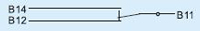
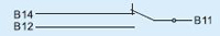
6.Alarming contact wiring diagram
The contact will not act when breaker is in the working condition, contact will not change his original position untill breaker trip freely,it means normal open turn to close,normal closing turn to open,it will recover to original position after breaker trip again

7.Undervoltage tripper
UVT should act reliable and push breakers to off when voltage reach 35%-70%rated supply voltage.When with less than 35% rated voltage, UVT should prevent breakers from closing,UVT ensure that breakers are closing when power supply voltage equals or surpass 85% rated voltage.

Controlling voltage: AC 50Hz 230V 400V
DC 110V 250V
P.S: Breaker can trip again and close on condition that UVT galvawize,otherwise will be broken
Table 10: Under-volt tripping instantaneous current and loss
Type | Instant current (mA) | Power consumption (w) | ||
AC 400V | AC 230V | Ac 400V | Ac 230V | |
TM1-63 | 10 | 13.5 | 4 | 3.105 |
TM1-100 | 9.75 | 14.25 | 3.95 | 3.2275 |
TM1-225 | 10.88 | 14.75 | 4.352 | 3.395 |
TM1-400 | 9 | 11 | 3.6 | 2.53 |
TM1-630 | 8.5 | 11 | 3.4 | 2.53 |
TM1-800 | 5 | 17.25 | 2 | 1.6675 |
8.Shunt tripping device
SHT is installed in A phase of breaker SHT should push breaker trip reliable at all requirements when
voltage is within 70%-110% of rated controlling voltage
Controlling voltage: AC 50Hz 230V 400V
DC 24V 250V
P.S:It is recommended for DC 24V controlling power to design circuit according to the right picture
KA:Means DC 24 middle relay contact current capacity 1A .

Table 11: Shunt tripping device instantaneous current and loss
Type | Instant current (mA) | Power consumption (w) | ||||||
AC 400V | AC 230V | DC 250V | SC 24V | Ac 400V | Ac 230V | DC 250V | SC 24V | |
TM1-63 | 0.28 | 0.434 | 0.341 | 4 | 91.6 | 76.1 | 90.7 | 96.2 |
TM1-100 | 0.288 | 0.425 | 0.341 | 4 | 96.8 | 73 | 90.7 | 91.2 |
TM1-225 | 0.313 | 0.412 | 0.341 | 3.87 | 112 | 68.8 | 90.7 | 85.3 |
TM1-400 | 0.197 | 0.325 | 0.4 | 3.87 | 67 | 62.3 | 94.4 | 100 |
TM1-630 | 0.199 | 0.314 | 0.4 | 3.87 | 68 | 58.2 | 94.4 | 100 |
TM1-800 | 0.538 | 0.898 | 1.134 | 5.22 | 163 | 153 | 120 | |
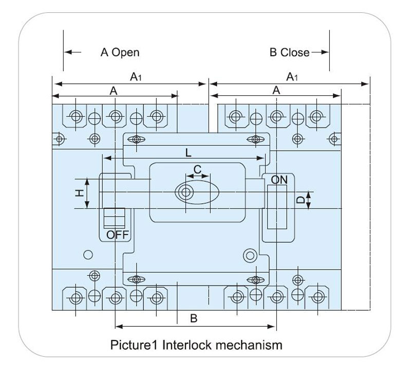
Interlock mechanism and relevent dimension picture1、marks13
 English
 Pусский<